bERLinPro
Linear Accelerators
The term “Linear Accelerator” (Linac) more describes the accelerator shape than its principle. Accordingly linac’s are straight structures applying a variety of resonator structures for electromagnetic fields, capable to accelerate a beam of charged particles.
In a simple frame a linear accelerator can be compared with the classical television tube. Here electrons are released from a heated wire surrounded by an evacuated tube and accelerated within the electric potential. Finally they strike the inner side of the screen to produce the tiny light dots, the tv frame is composed of. The voltage, the electrons have passed, is a measure for their energy gain. In a TV with a voltage of 20 000 V the final electron energy will be 20 000 eV (eV = electron volt) or 20 keV. Since the applied voltage is dc-powered these kind of accelerators are referred to as electrostatic. One major drawback is that the electrons (or the charged particles in general) reaching the high potential side of the accelerator cannot be further accelerated. Field emission at highest electric fields leads to a limiting breakdown voltage. The highest energies that have been reached are a few tens of MeV (MeV = million electron volt).
In Linacs this limitation is overcome by applying oscillating electromagnetic field for acceleration. These radio frequency (rf) fields are excited in so called cavities.
What is a Cavity?
Cavities are metallic pill box or tube shaped resonators for electromagnetic fields. Once an electromagnetic wave is coupled into a cavity it travels from wall to wall, where it is reflected each time. Depending on the dimensions of the cavity the wave travels with frequencies from ten’s or hundred MHz (MHz: 10^6 oscillations per second) up to GHz (10^9 oscillations per second). If the length of the cavity is chosen to be half the electromagnetic wave length a resonating, so called “standing” (nevertheless still oscillating) field of extreme strength (tens up to hundred million volt per metre) can build up. A charged particle, passing such a cavity, will be strongly accelerated if electric cavity field and particle velocity are equally directed. Accordingly a particle is decelerated, when it passes the cavity while the electric field is oppositely directed to its motion. For this reason in linacs as well as in storage rings (where energy losses are compensated by rf fields) not a cw beam but a bunched one forms up.

Fig.: Oscillating Electric Fields in an RF Cavity
Klick on the figure to start animation: Particles passing the cavity from the left to the right would be accelerated by green arrows and decelerated by red ones (due to sign conventions those particles need to be positively charged - for electrons it's vice versa)
By switching from static to oscillating fields a cascading of accelerating structures becomes possible and thus extreme electron energies in the tens of GeV range (GeV = 109 eV) can be reached.
Applications of linac generated high energy particle beams is multifaceted and cover many scientific fields. With regard to the production of light a high energy electron beam out of a linac could be sent through one or more insertion devices to generate high brilliance synchrotron radiation.
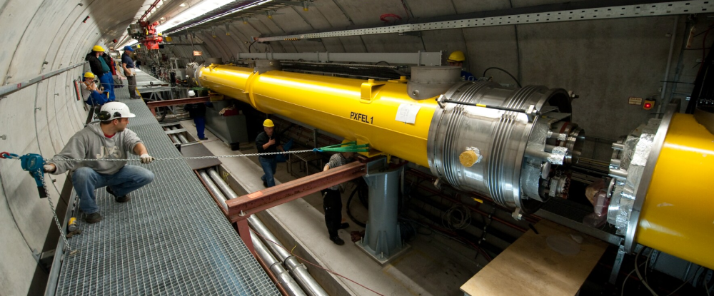
Fig.: Assembly of a Cryogenic Module, housing eight superconducting TESLA cavities, in the FLASH linac, DESY, Hamburg, Germany
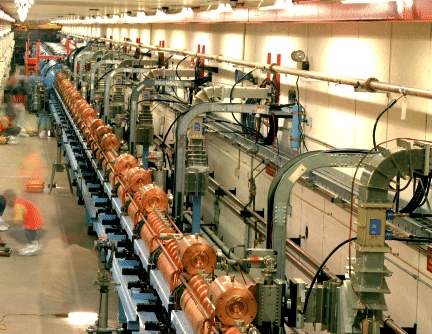
Fig.(top): Tevatron's Hydrogen-Ion Linac, based on normal conducting copper cavities, Fermilab, Battavia, Ilinois, USA
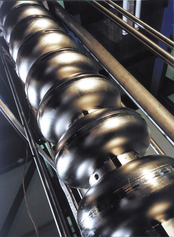
Fig. (right): TESLA Cavity, superconductiong niobium nine cell resonator
Free Electron Lasers
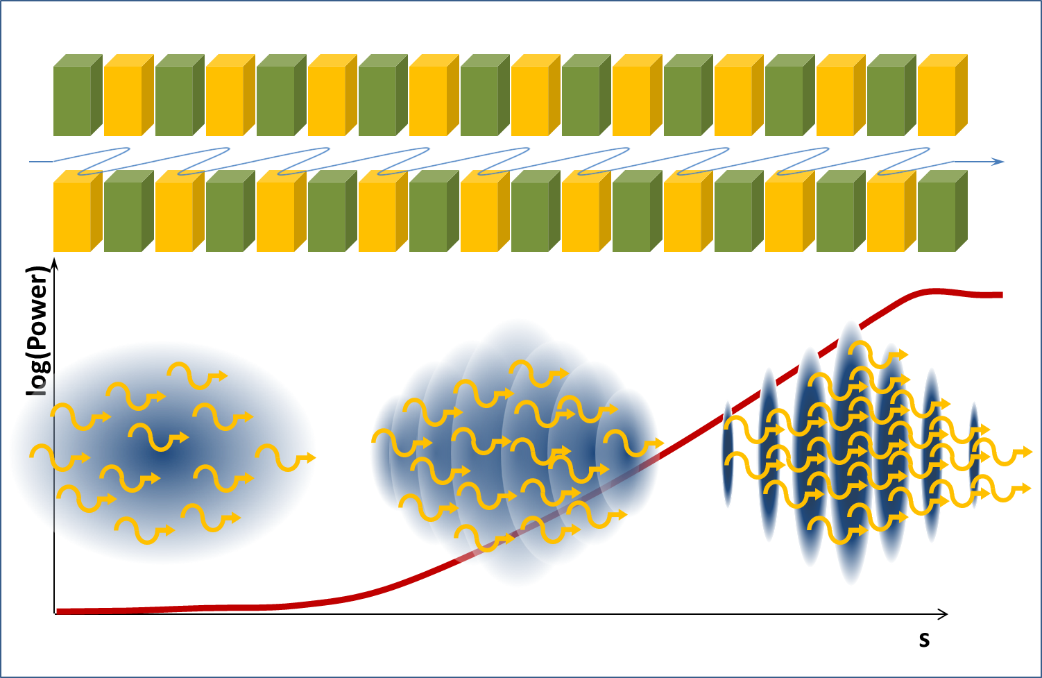
Fig.: FEL Principle: in the first part of the undulator the phases of the emitted photons are equally distributed - so most of the power chancels out again in such an uncoherent emission process. In the middle part the interaction of the self generated radiation field with the electrons imprints firstly a momentum and secondly a density modulation - called bunching. The distance between the centers of the evolving microbunches is the wavelength to be enhanced by the FEL. With increasing bunching the fraction of coherent emission rises, leading to an exponential growth of radiation power in the middle and third undulator part.
Today's 4th Generation, high brightness synchrotron radiation facilities work on the principle of the “Free Electron Lasers” (FEL). In an FEL the accelerated electron beam passes a chain of insertion devices. While passing it interacts with the self emitted light (SASE FEL) or with externally coupled in, co-propagating light (Seeded FEL). As a consequence a micro fragmentation inside the bunch can develop, allowing for a coherent emission of light (equal phase of all waves) and thus an enormous increase in intensity compared to the normal (incoherent) synchrotron radiation. The start up of the FEL process sensitively depends on an excellent beam quality. Most important is an ultra high electron density in the bunch, only reachable with a high quality source together with sophisticated beam manipulation techniques during linear acceleration. For that reason at present linacs are predistinated as FEL drivers.
FELs produce more intense radiation than any other Synchrotron light source, generating power levels that evenly exceed the probe's destruction limts. Due to a repetition rate, very low compared to that of storage rings, experiments that depend on an even average intensity in time can not use FEL radition. For these type of experiments the time structure of ERL based light sources is much better suited.